Site Directory
Projects List - Page One
Click for alphabetical list of all the projects.
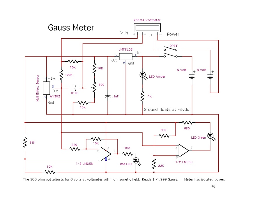
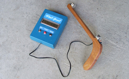
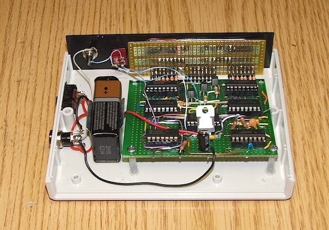
Gauss Meter
Wind Meter
Infrared Tachometer
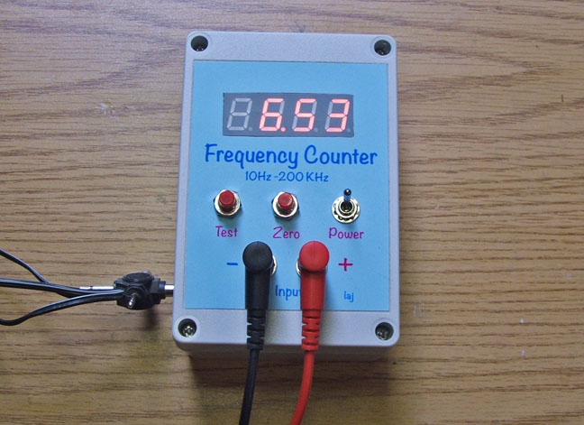
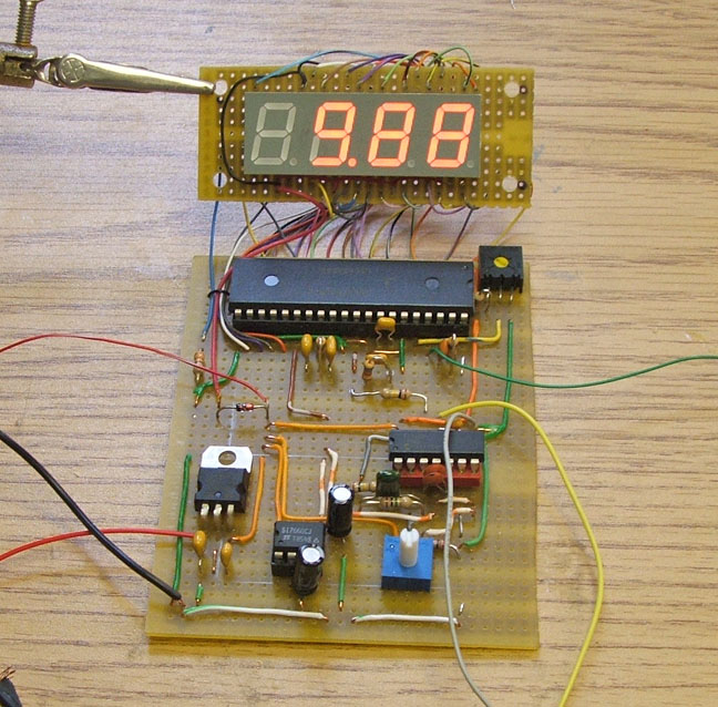
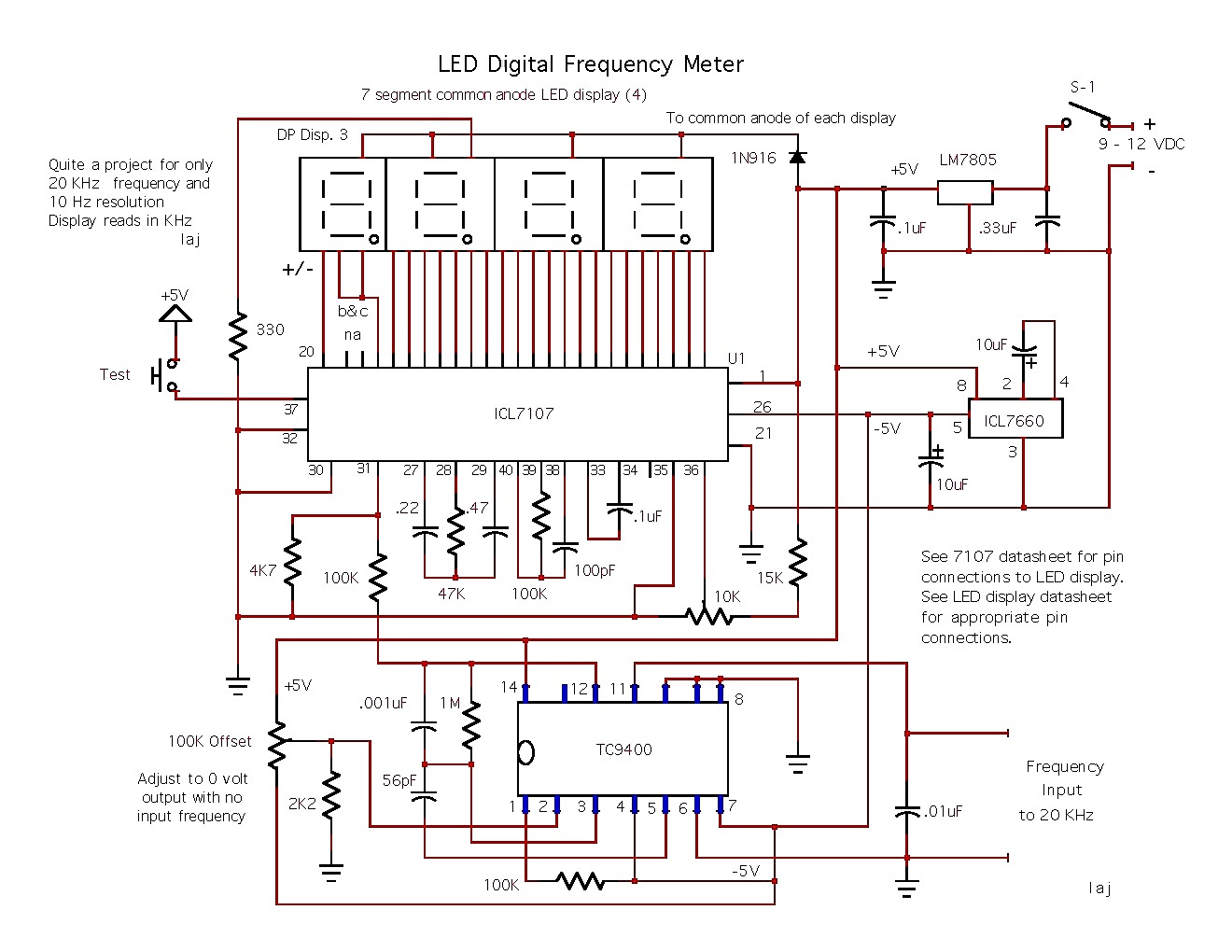
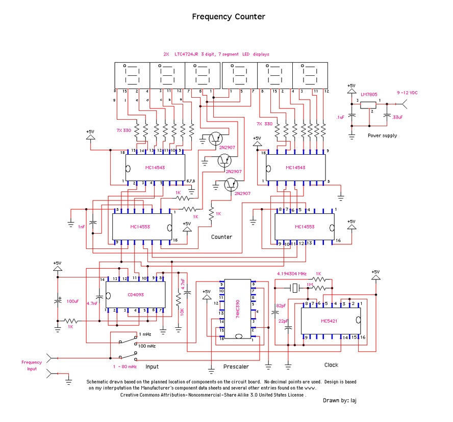
Frequency Counter
Function Generator/Frequency Counter
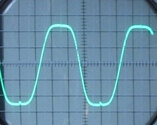
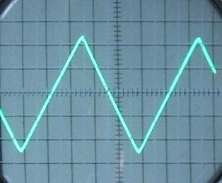
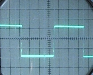
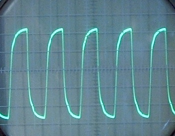
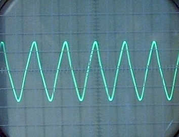
(Oscilloscope Traces)
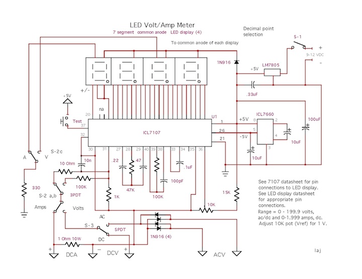
Digital Volt/Amp Meter
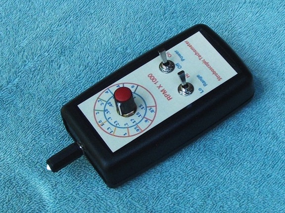
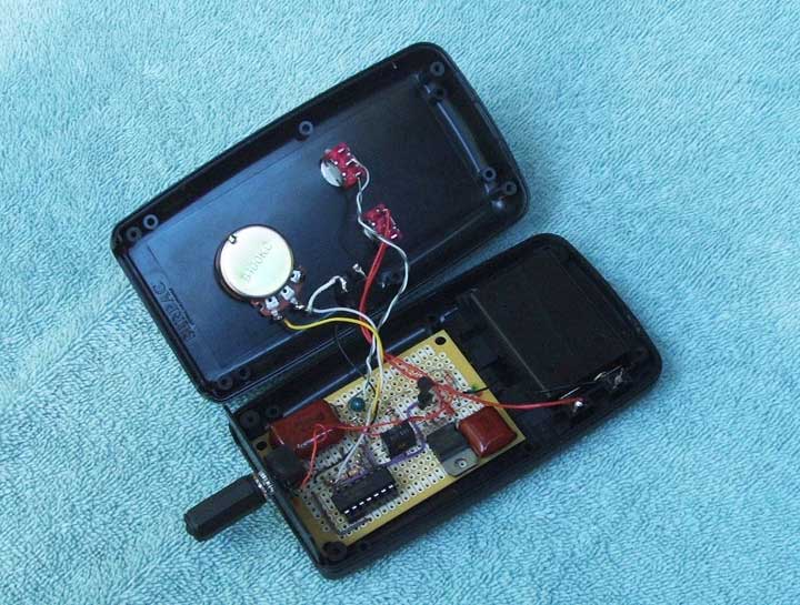
Stroboscopic Tachometer
Capacitor Meter
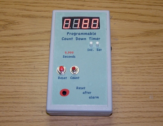
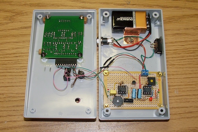
Programmable Counter
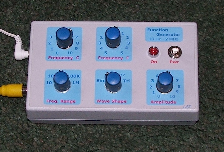
Function Generator
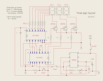
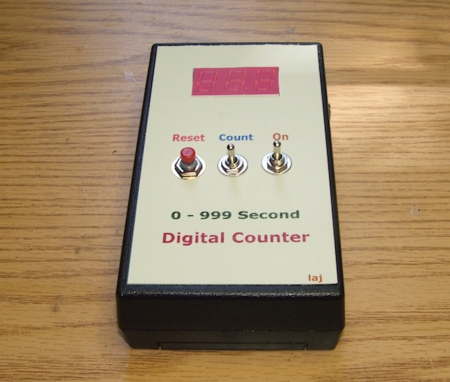
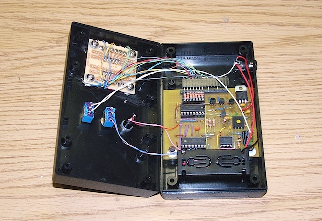
Three Digit Counter
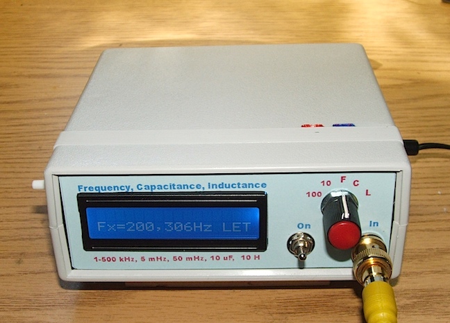
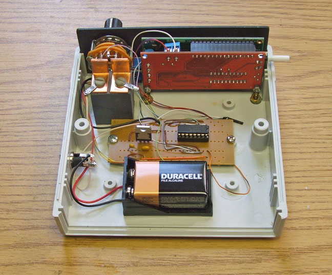
Frequency, Capacitance, Inductance Mater
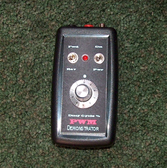
Pulse Width Modulator
Crystal Tester (Transistor)
Ultra/Audio Tone Generator
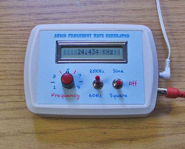
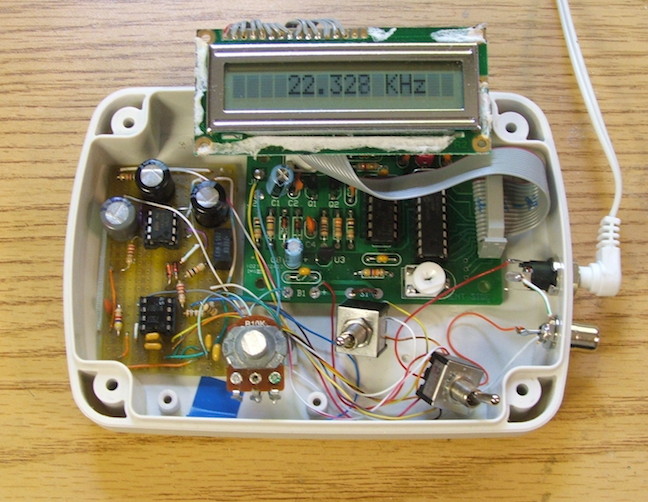
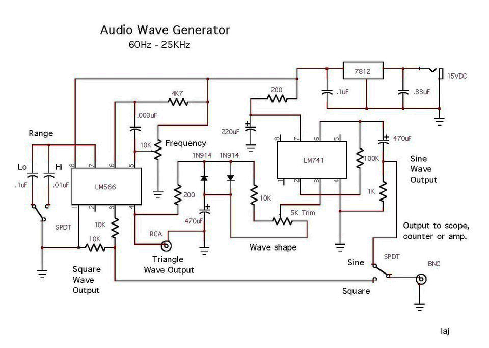
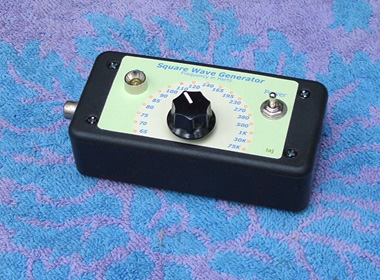
Audio Frequency Wave Generator
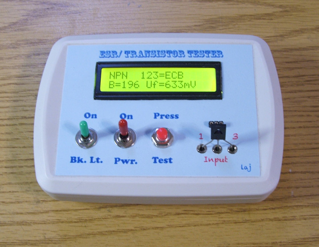
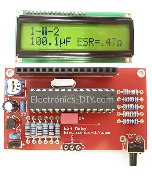
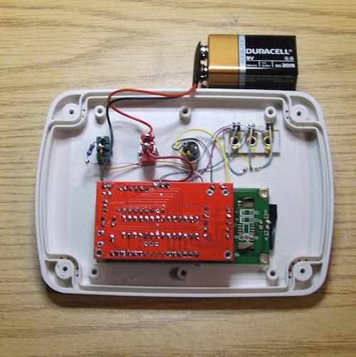
ESR/Transistor Tester
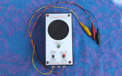
Transistor Tester
1.25-30 VDC 3 Amp Power Supply
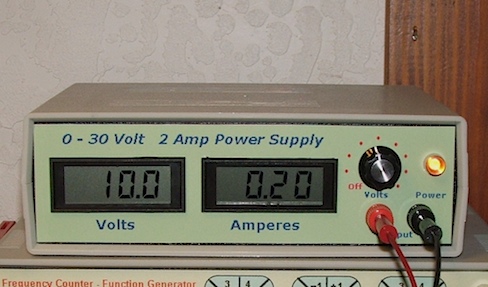
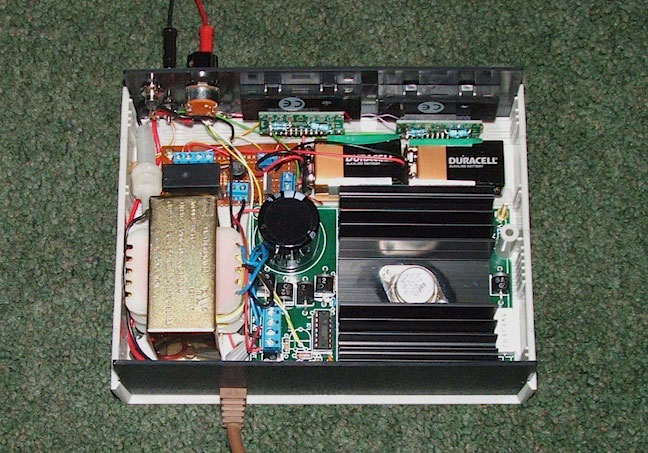
2 Amp Power Supply
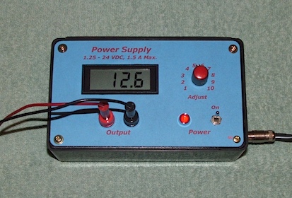
1.5 Amp Power Supply
Dual Multi-Voltage Power Supply
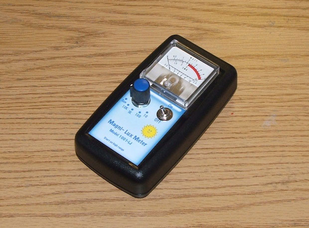
Lux Meter
NE555 AF/RF Generator
Crystal/Oscillator Tester and
Frequency Counter
(Oscilloscope traces of crystal & oscillator)
LC Meter
Zener Diode Tester
Digital Oscilloscope
D32 Oscilloscope
Programmable Counter
Function Generator II
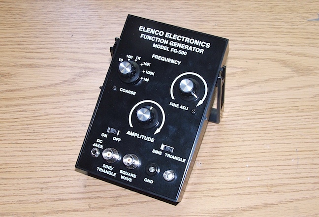
FG-500 Function Generator
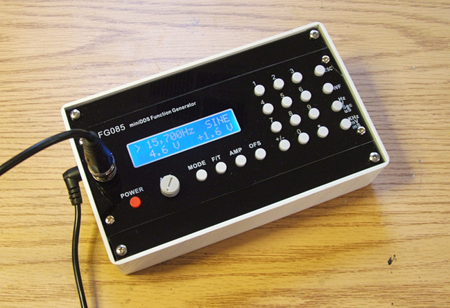
FG085 Function Generator
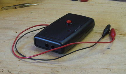
Wave Generator
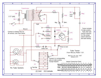
Tube Tester Schematic
Here is an alphabetical list of all the projects.
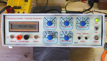
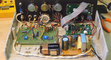
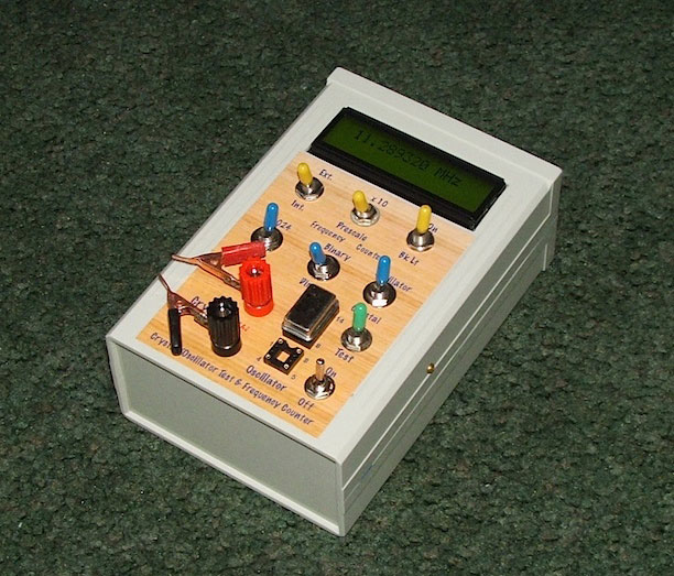
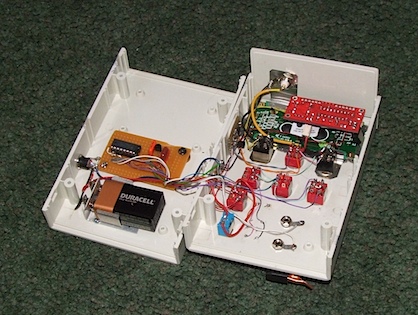
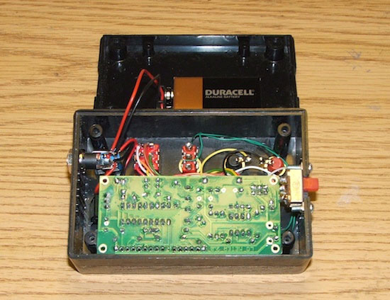
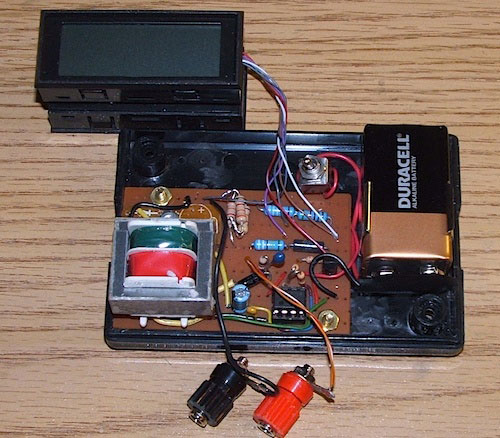
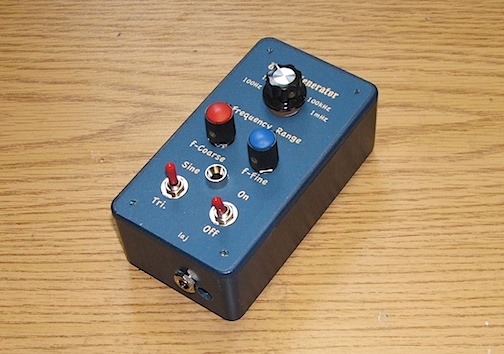
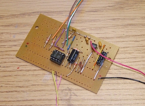
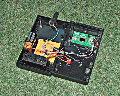
My Function generator/Frequency Counter was built by combining two kits. The function generator is a kit from Jameco Electronics and the frequency counter is a kit from CallSaver Corp. It measures from 1 Hz to 50 MHz.
The schematics are in two parts - Function Generator, click image.


