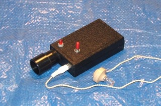
Simple Bat Detector designed
by Tony Messina
(frequency division type)
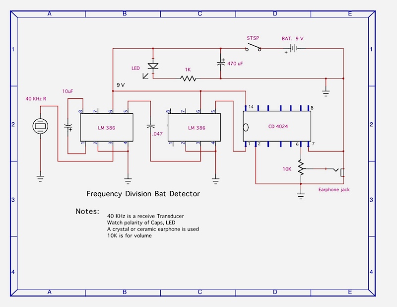
Simple Bat Detector designed |
Here is a schematic drawing of a Frequency Division |
A bat detector is an electronic listening device that will allow us to hear the bat chirps and buzzes. There are several types of bat detectors being used by bat listeners.
Frequency Divider
Heterodyne
Time Expansion
DSP (digital signal processor)
Here we will discuss the Frequency Divider and the Heterodyne detectors as these are within the means of most casual bat listeners. For serious research, a detector can be quite expensive - thousands of dollars. For the casual bat listener, a detector can be purchased for less than $100. or built as a kit for less than $50. Those folks who are handy putting together electronic circuits can build a detector.
Frequency Division Detector:
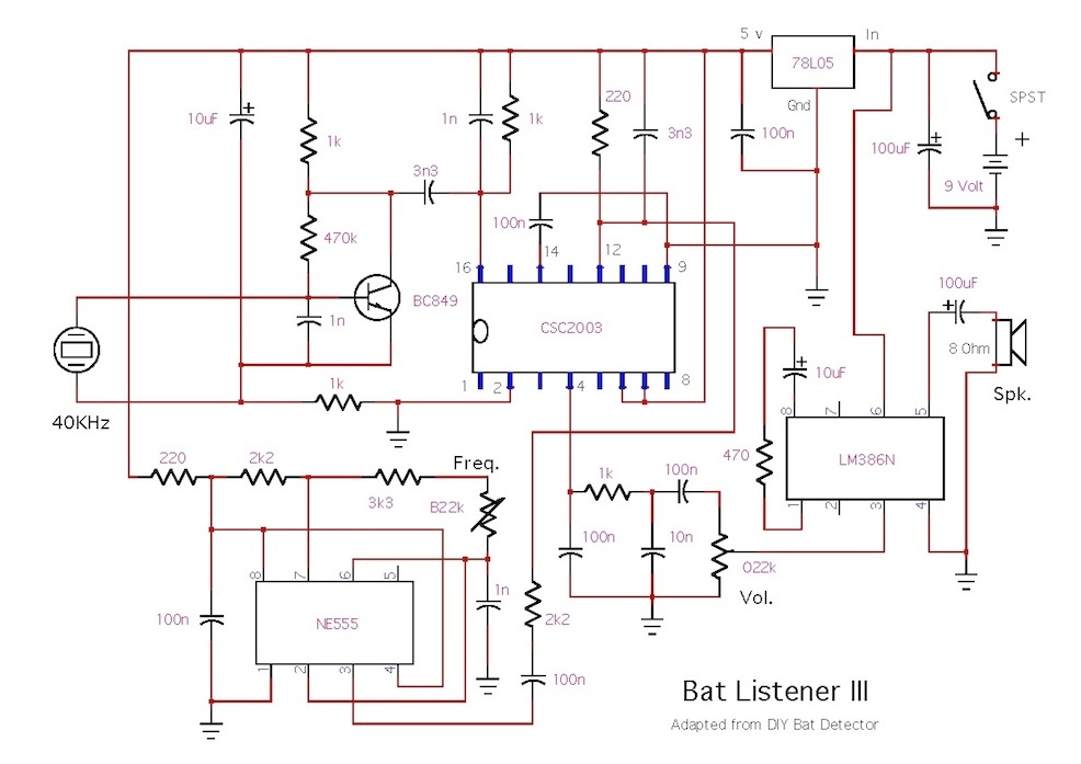
This detector picks up the bat ultrasonic sound with a receive transducer that is sensitive to the bat frequency, in the area of 40KHz (40,000 cycles per second). The signal is then amplified and fed into the frequency divider where it is divided by 16. A 40KHz signal, for example, would then be audible to we humans at 2.5KHz. This 2.5 KHz signal can be amplified in one or more additional stages to drive the earphone, speaker or headphones. The circuits can be quite simple, using a few amplifier ICs and a binary divider IC as the main components. A good and easy to build Frequency Division detector is described in a web site by Tony Messina. See his web site at home.netcom.com/~t-rex/BatDetector.html The "frequency divider" detectors work well and have a good range. They produce no background noise and will fit easily into your pocket. They can be used with headphones or a small speaker mounted in the case.
 Bat Detector by Larry (heterodyne type) |
Heterodyne Detector: |
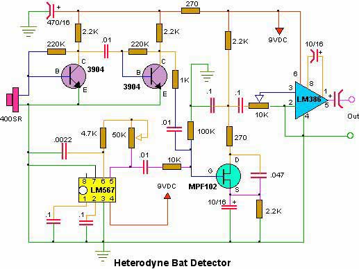 Schematic of a heterodyne bat detector.
Click image for a larger JPEG view. |
The circuit shown here is for a heterodyne bat detector. This was first presented by Popular Electronics magazine as an Ultrasound Detector, in 1994. Construction is straight forward and can be laid out very much as the schematic shows. I built mine on a 2-3/4"X1-3/4" IC project board. I found that using shielded cable for connection to the level and frequency controls helped reduce any feedback. I think in the next one I build I'll use LM386 amplifier ICs in place of the input transistors so that I can get a little more gain. |
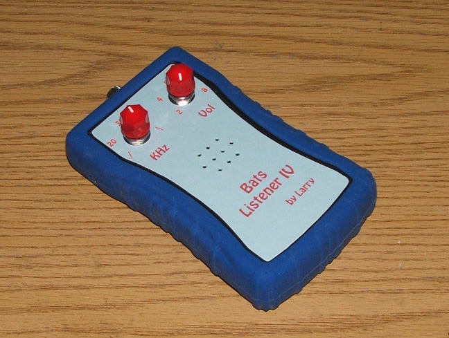
 Here is another heterodyne bat detector built with a similar circuit to the one above. |
|
This Heterodyne Bat Detector was built with a circuit similar to the one above except, I experimented using ICs for the first amplifier stages instead of transistors. The first stage is a LM358 op-amp with an adjustable gain trimmer and the second stage is a LM386 set up for 20 gain. Also, the output stage is a LM386 set up for adjustable gain of up to 200 with a 10uf capacitor and a 10k trimmer pot. Included are a speaker and a headphone jack. The eyes of the bat flash when a bat sound is detected. |
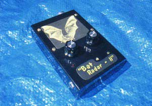
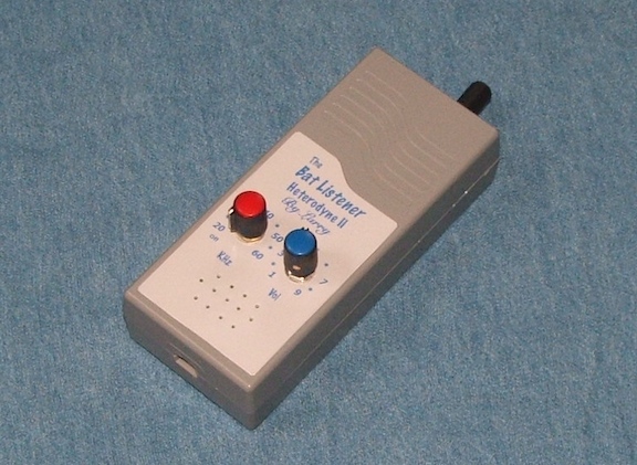 The Bat Listener (Heterodyne II) Click for larger image |
 The Bat Listener (the inside electronics) Click for a schematic in JPG format | The Bat Listener |
 A heterodyne built with a purchased kit. |
|
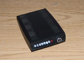
My newest Bat Detector is built from a kit supplied as "Bat Detector DIY," (a design by Franzis). The circuit board is tiny so I was able to install it in a smaller enclosure than the box that came with it. The detector works very well with little background hiss and good sensitivity. For this enclosure I had to replace the speaker with one that is 4mm thin. I installed an earphone jack which always helps. The enclosure is from "Polycase." |
|
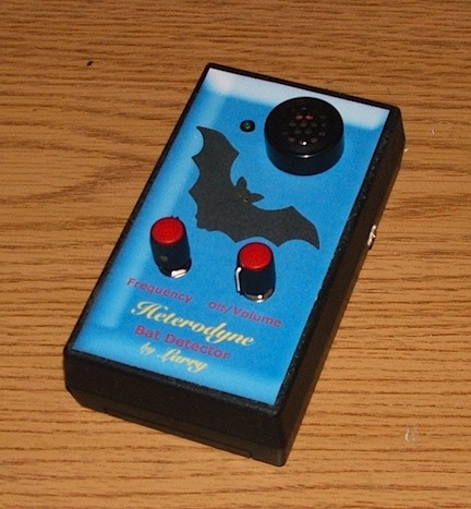
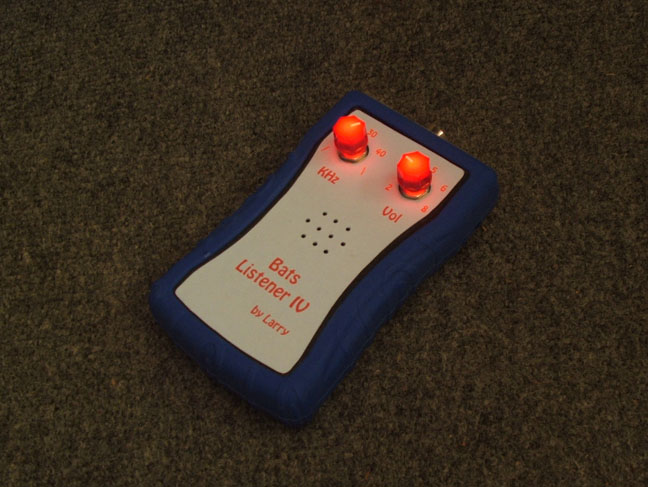
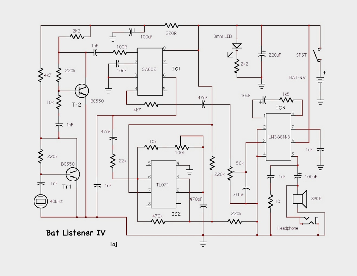
Another Bat Detector, similar in appearance but a bit larger and of my own making is shown at right. The circuit is built with BC550 transistors at the front end, a TL071 OpAmp oscillator, a SA602 Mixer and a LM386 output amp. The detector is very sensitive, generates good volume and produces little background noise at most frequency selections.One of my better arrangements. A novel feature of this one is the lighted control knobs. The potentiometers have clear plastic shafts where I have inserted 3mm LEDs. |
 My new heterodyne built with refinements. |
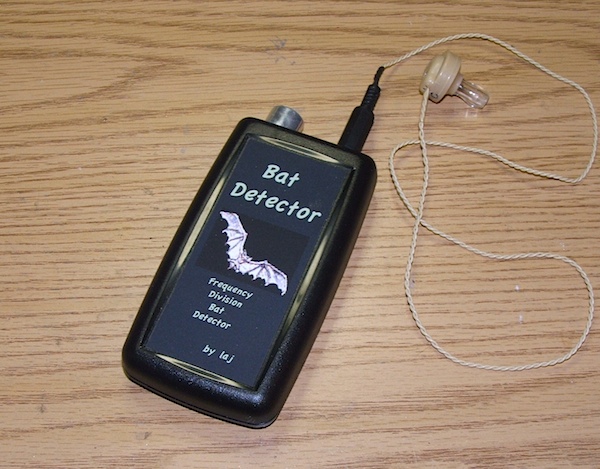 Frequency Division Bat Detector Click for larger image. |
 The Circuit Board The Circuit Board Click for larger image. | New FD Bat Detector My new Frequency Division bat detector is built from the original Tony Messina design with some changes in parts value and a few additional parts. After some experimenting, I got it to work as well as the original Enhanced Simple Bat Detector. The small case goes neatly into a shirt pocket. Already, I have listened to bats in our garden at about 75 ft. distance. The schematic for this detector is similar to the first one on this page, the Simple Bat Detector.
|
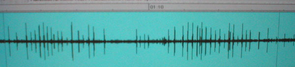 Waveform of a bat flying near our horse paddock. |
This picture (a waveform) of bat sounds, was recorded using a heterodyne bat detector and a hand held tape recorder. The sound from the recorder is converted, using computer software, to a picture. Here we can see the bat is making 10 - 12 chirps per second. Near the center there is a section of concentrated sound where the bat buzzed after an insect. The buzz consists of many more chirps per second as the bat speeds up its echolocation signal so as not to miss its prey. This waveform duration is about 8 seconds as the bat circled near my head. The dark horizontal line along the center is background noise from the recorder. |
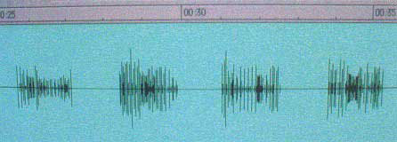 Waveform of a bat-synthesized sound. |
Here the waveform is a synthesized bat sound made with my bat simulator "Bat Amigo". The signal is emitted from the transducer in spurts at about 40KHz. The chirps sound like a bat, heard through a bat detector but the pattern is unlike that of a bat. This little device is handy for testing the operation of my bat detectors and for checking, comparatively, the range. |
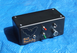 Bat Buddy |
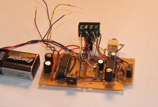 Bat Buddy circuit board |
"Bat Buddy" is my bat simulator, a little-black-box which houses an electronic circuit. It makes ultrasonic sounds in the frequency range of some common bats. The circuit has three oscillators which simply generate three frequencies which are mixed, amplified and applied to the transmit transducer. The LED flashes as the ultrasonic sounds are generated and it has an output jack so I can measure the frequency with my oscilloscope. With Bat Buddy I can adjust the output level to be more comparable with what we are hearing from real bats. Also, the type of output is selectable for bat chirps or a sustained signal for testing bat detectors. The frequency range of Bat Buddy is variable from 25 KHz to 60 KHz. |
 Bat Simulator SchematicClick for a larger image and parts list in JPEG format. |
The schematic drawing shown here (with my modifications) was found on the NJSAS web site. See links page. The frequency adjustment is made with R5 and the output level with R10. D1 is shown in the parts list as a bridge rectifier but I actually used four 1N914 diodes wired as a bridge. The ICs are: IC1, 74HCT04N, a hex inverter, IC2, 74HCT08N, a quad AND gate (two of the AND gates are used) and LM386, an audio amplifier. C1, C3, C4 and C6 are electrolytic capacitors—note polarity. The ultra-sonic frequency can be read by connecting from J1 to a frequency counter or a multimeter with frequency read out. |
 Audio/Visual Bat Detector |
Here is another of my experiments in building bat detectors. This one displays a visual of the bat chirps with LEDs as well as providing the sound. The video section is built around a CD4017BE decade counter. At the front end a high gain amplifier is built through three of the op amps in a TL074CN quad op amp IC. The fourth op amp is wired as a oscillator to drive the decade counter. |

Thanks for your visit. If you have any comments or questions, please e-mail: wolfden@terragon.com